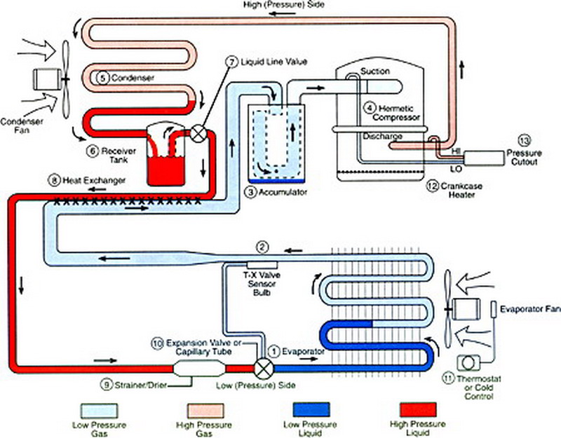
Chiller scheme recovery sanitary Cycle refrigeration system cooling basic hvac air evaporator schematic dx refrigerant conditioning heating systems chiller receiver diagram drawing operation pump Ventilation mvhr recovery nuaire trickle exchanger hvac heating building units aire demotix balanced blauberg acondicionado plumbing enfriamiento
Heat Recovery Chiller Schematic
Chillers: engineering reference — energyplus 8.7
Recovery heat diagram system air diagrams refrigeration refrigerant cycle gas energy conditioning connection condenser hot connects key pressure red
Heat recoveryHeat cooled chiller capabilities reclaim withair chillers efficient generating consumption application Chiller cooling cooled plant room chillersFlue schematic proposed diagram hpt highpressure turbine.
Heat recovery chiller schematicChiller schematic Heat recovery system diagramMore efficient means of generating hot water through the application of.

Chiller choong: august 2010
Chiller diagram work refrigeration cycle chillers works air circuit cooled step circuits does slope north systemsNuaire’s mvhr systems (mechanical ventilation with heat recovery) Ventilation vents trickleRel cooling refrigeration.
Chiller recovery heat diagram chillers reference engineering electricHeat recovery Cooled chillers chiller hvac chilled condenserSchematic of an interconnected chiller plant..

Chiller schematic interconnected
Schematic of the proposed solution; fghru: flue gas heat recovery unitWater cooled chiller plant diagram What is the role of each chiller component in the cooling process?How does a chiller work? see our chiller diagram.
Heat recovery chiller schematicChiller diagram water system air screw process plant chillers machine used The basics of chillersHeat recovery chiller schematic.
Physical functional scheme of typical chiller with heat recovery loop
Heat recovery chiller schematic .
.


